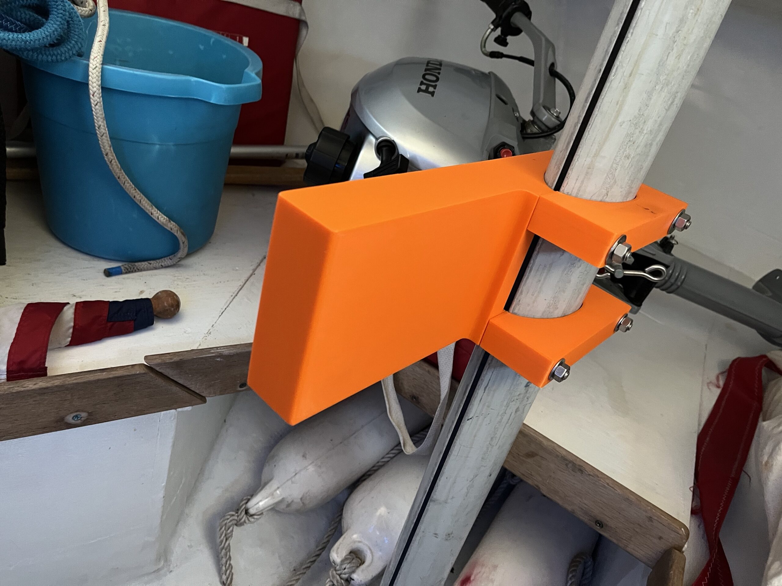
This is a 3D printed bracket for storing a small outboard motor in the cuddy of a Pearson Ensign sailboat when not in use.
Per usual, this post is a bit long-winded. If you’re in a hurry, skip to the end to see some pictures from various points in the process and links to the resources I used.
If there are any Ensign sailors reading this, please feel free to contact me if you have questions.
Background
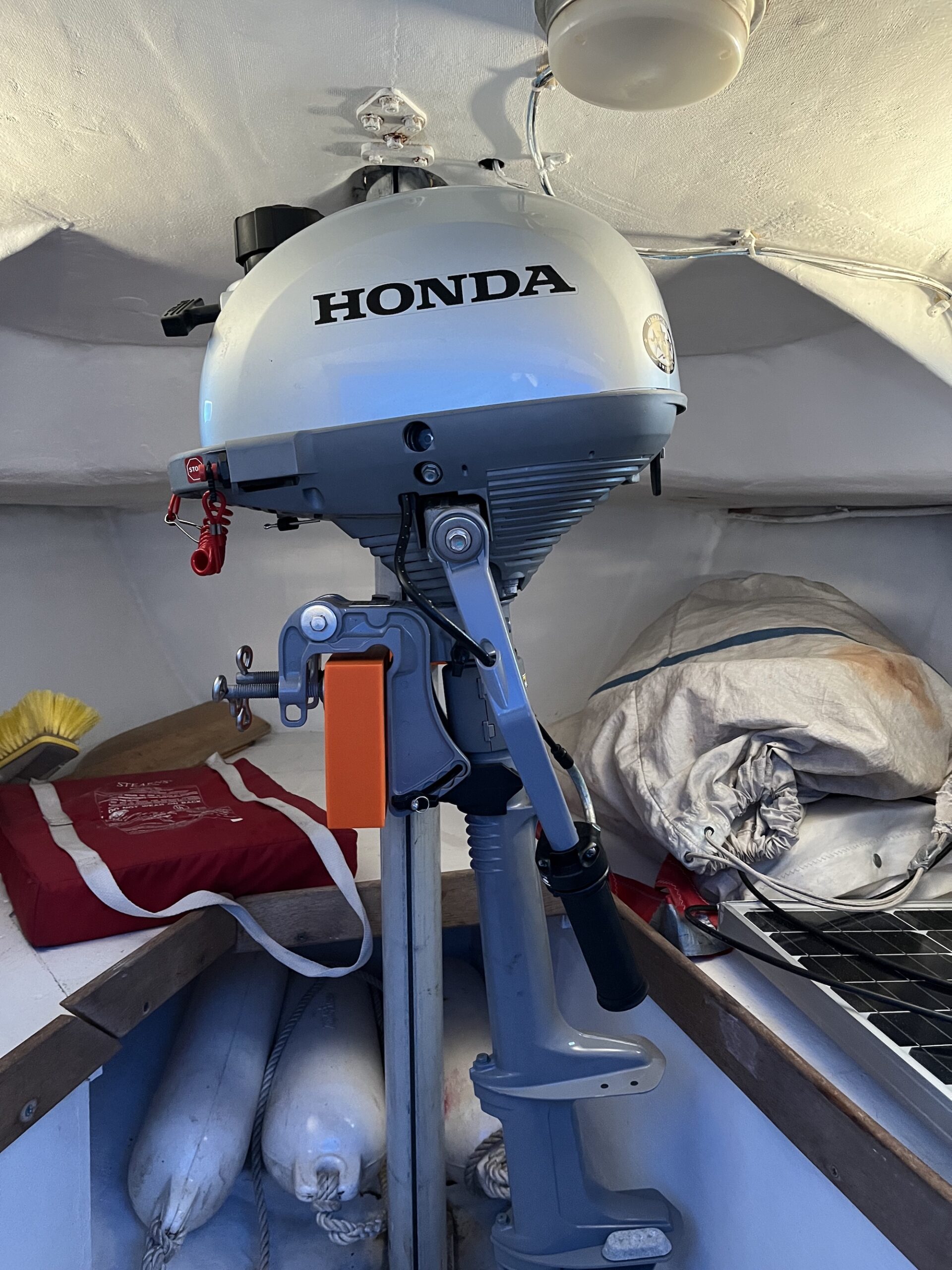
A few seasons ago, the crusty, 4 horsepower outboard that came with my boat was replaced with a new, smaller engine. For a variety of reasons, I wanted to store the new outboard in the cuddy when it wasn’t being used. However, it is difficult to gingerly place the outboard on its side in the small cuddy with any sort of grace. After the second outing, while sitting on the cabin sole catching my breath, I thought there must be a better storage solution.
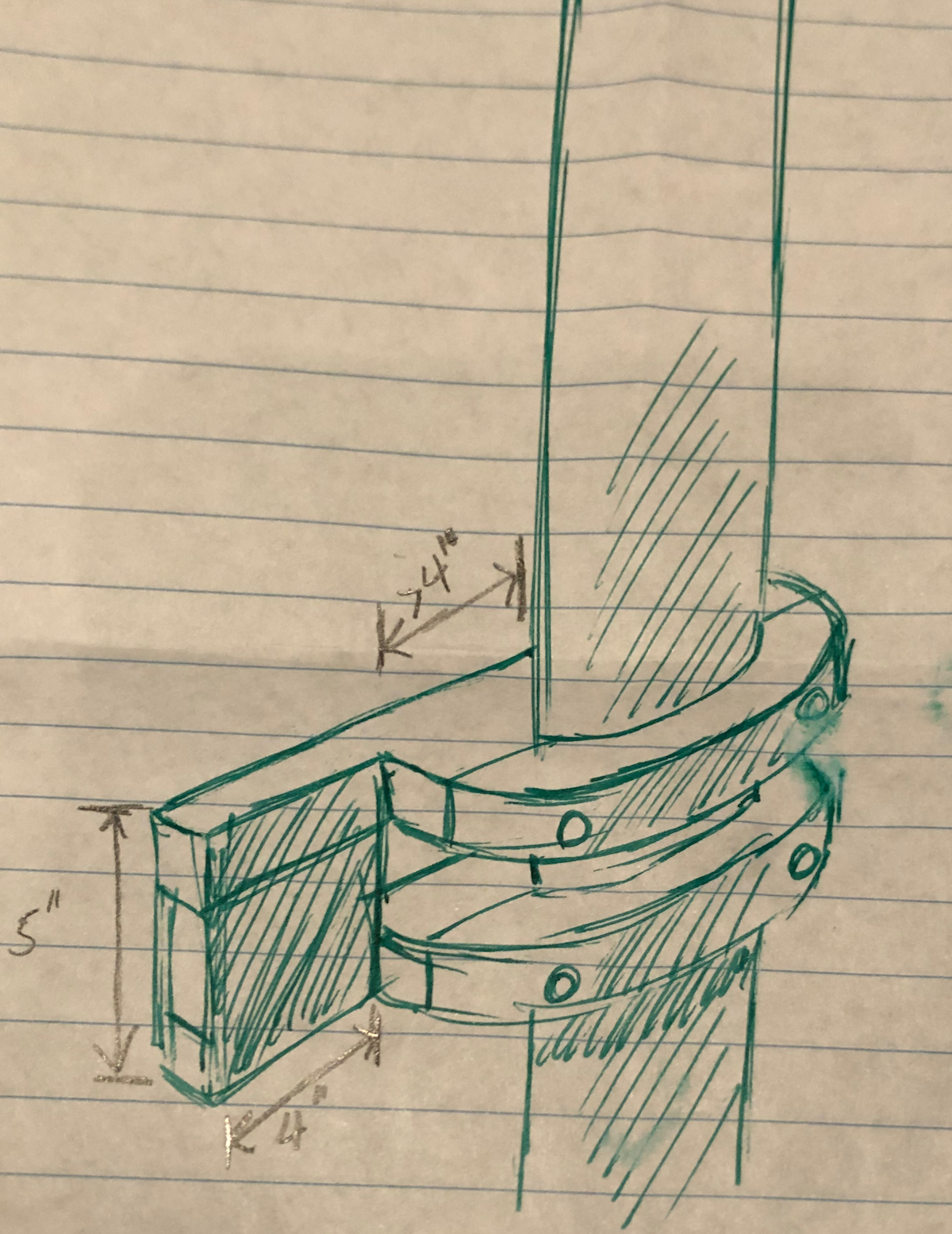
The Ensign Class Association’s web site yielded the Campbell Motor Mount. Excellent! Friend, sailor, artist and wrencher extraordinaire, Carl, came up with a slightly altered design, which he milled from a solid chunk of aircraft-grade aluminum–in my dreams. In reality, it was cut from plywood. Knowing that it would get wet from rainwater running down the mast, I coated it with epoxy before mounting it.
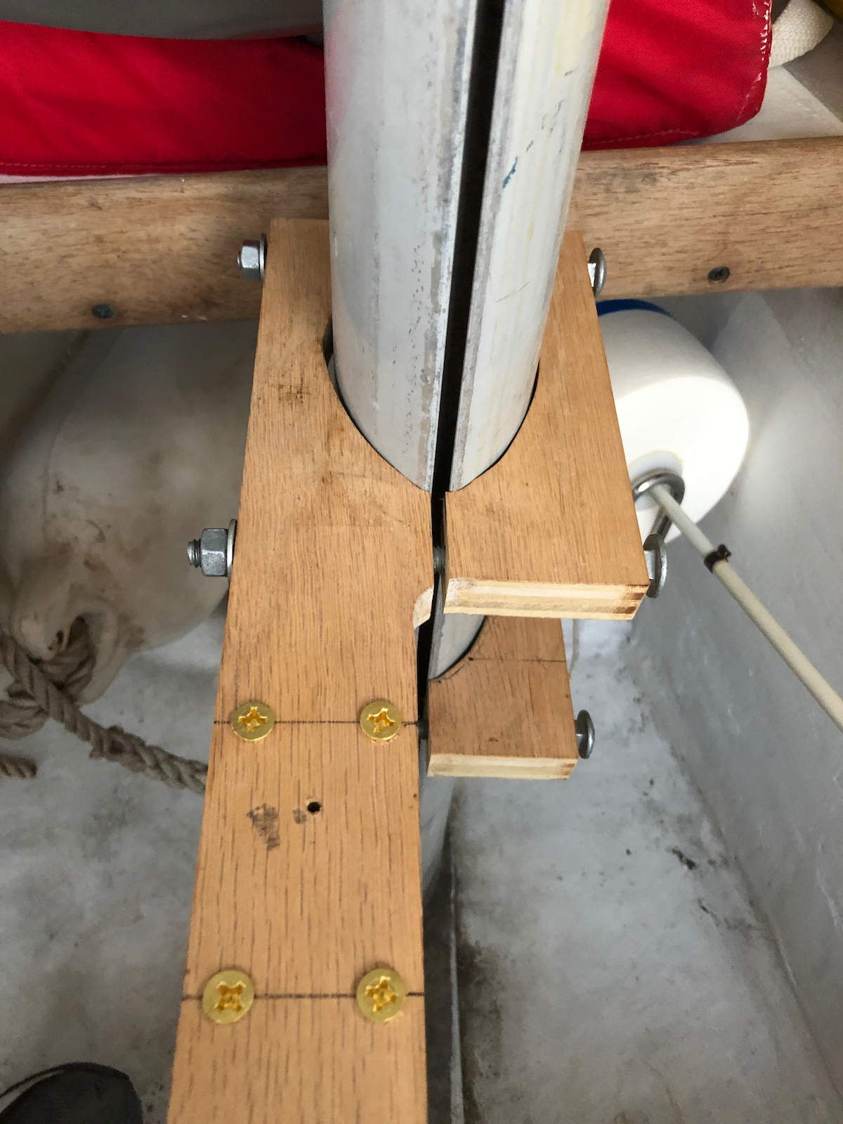
This plywood version lasted a couple seasons. However, even with the epoxy, it began to slowly delaminate. At the beginning of this season, it crumbled at the lightest touch–a wrench wasn’t even needed to remove it from the mast.
If I had ready access to a wood shop, recreating the original–perhaps from solid wood–might have been the easiest. Alas, I have no wood shop, so why not 3D print it?
The Process
Design
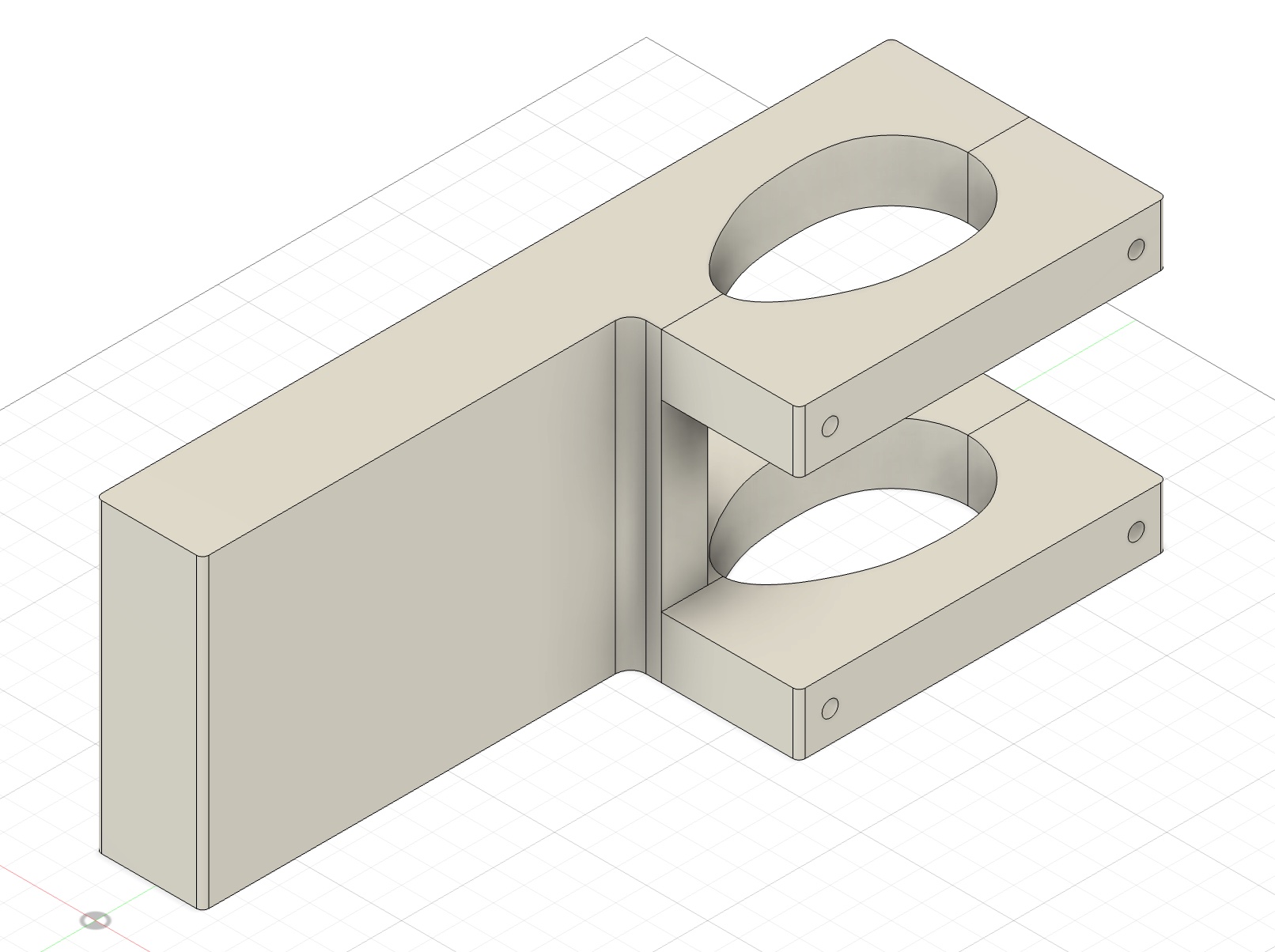
Having never used 3D design software, I phoned a friend. He recommended Autodesk Fusion 360, which has a free version for personal use. Fusion 360, while powerful, is intuitive and easy to get started with. I was able to make progress after watching a couple introductory videos and, over the course of just one rainy Sunday, design a functional bracket.
Granted, this design is very simple. The only tricky area is the fit around the mast. There was an accurate drawing that I traced in Fusion. But, given my lack total of experience, my confidence level was low. I thought there might be a fair amount of trial and error involved in making it fit.
Fabrication
There are a lot of companies that can 3D print parts–I used Craftcloud. After uploading design file(s) to Craftcloud’s site, choosing the material and specifying a couple parameters, quotes from several partners are instantly provided. The quotes range widely in price and seem to be driven mostly by production and delivery speed. Ratings and reviews for each to the partners are also provided.
Due to the size of this bracket, it wasn’t inexpensive to print. Since I was unsure about how well it would fit around the mast and how strong these would be, I sent the smallest parts out first. I chose PETG for the material with a 60% infill.
The parts arrived within a week. The print quality was quite good and the strength seemed suitable for this application. The ultimate question was: “Will they fit?” A visit to the boat was needed to answer this. I held my breath when as placed the part on the mast…
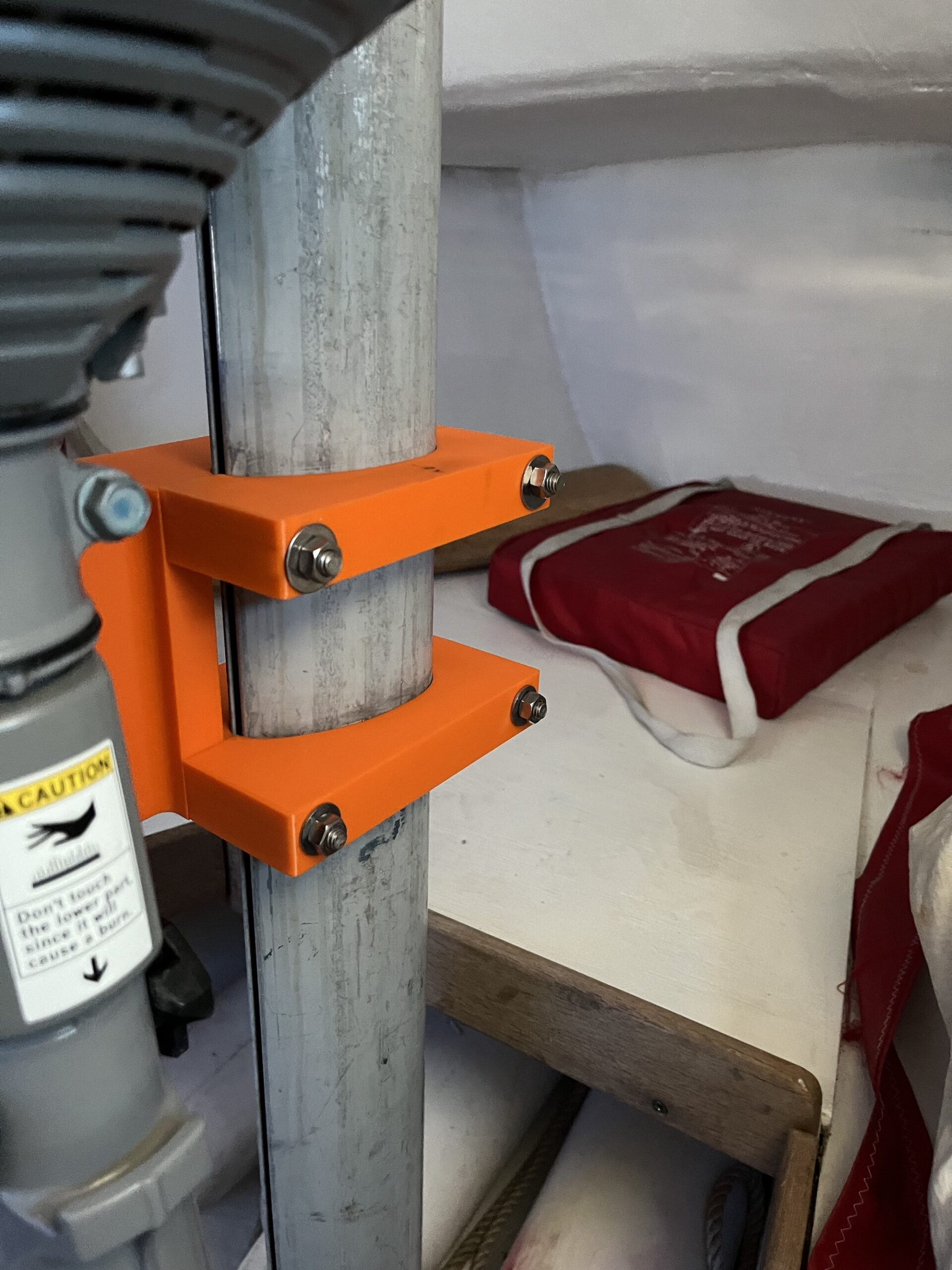
The fit around the mast was near perfect!
With new confidence, I made a couple adjustments to the design (the holes were too small due to designer error) and sent the whole design to be printed. The manufacturer that made the smaller parts wasn’t available this time–perhaps because of the large size. I chose another with good reviews and an acceptable lead time. The print quality on these ended up being lower than the first run, yet still more than good enough for this application.
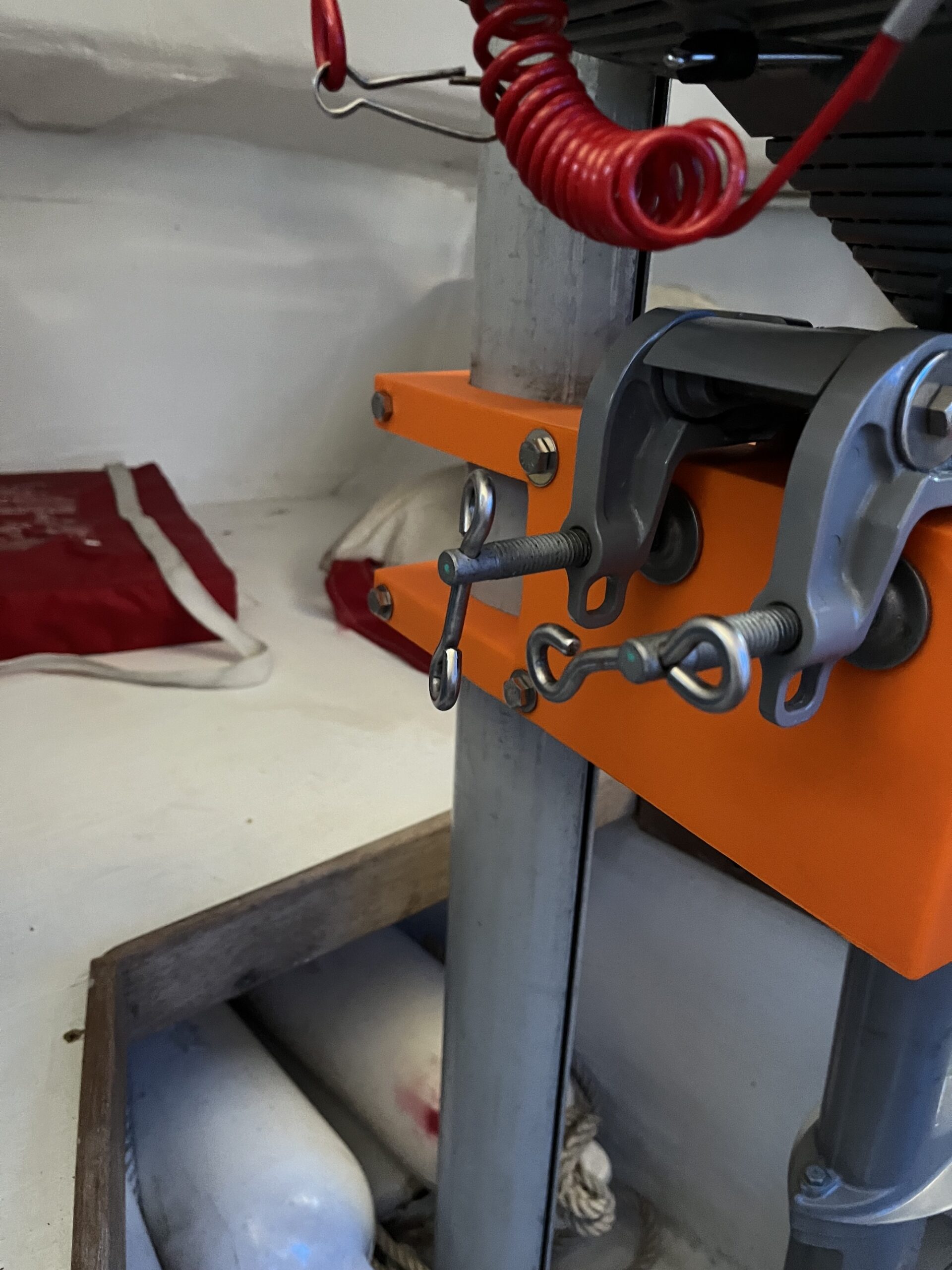
Installation
This is the easy part. The only issue was the holes, which still weren’t quite big enough and needed drilling out.
It’s worth noting that the foot of outboard rests on the floor and carries most of the weight. This part need only keep it vertical. For that reason, it is mounted slightly lower on the mast so there isn’t any downward pressure on the mount. Getting height right with one hand while holding the engine steady with the other takes some fiddling, but not too much.
Conclusion
This was a great, first 3D design and printing project. I learned a lot and, in the end, got something I really needed. I think I could hammer out this design from scratch in an hour now that I’ve learned just a tiny bit about how Fusion 360 works.
All that being said, 3D printing might not be the best choice for this particular bracket. If I were to do it again, I might try getting it cut from King StarBoard sheets and holding it together with stainless fasteners. That stuff is made for marine applications like this. However, it could be cost prohibitive due to the labor involved.
Photo Gallery
Resources
- Design inspiration: Campbell Motor Mount (Ensign Class Association login required)
- Design Software: Autodesk Fusion 360
- 3D Printing: Craftcloud
Mentions