 This is a very simple Arduino shield with only one purpose: to Serve as a timer for practicing the Pomodoro Technique®. If you’ve never heard of this technique, you might want to have a quick peak at their site before reading on.
What follows is fairly long winded. If you’re not all that interested in the process, and just want some links to the Arduino sketch, schematics and board layout, skip to resources section at the end.
Background
I wanted very simple project that could be completed in a short amount of time and I wanted it to be useful. Since I am sometimes prone to fits of procrastination, I am familiar with the Pomodoro Technique® and find it to be a good way to help get things done. In my environment, the prescribed tomato kitchen timer is too noisy. So, a specialized pomodoro timer to use at work makes for a great, simple project.
The Process
- Sketching: With an understanding of what I wanted to build, I made some rough sketches. A tiny project like this doesn’t require it, but sketching really helps in forming a better understanding of what the final product will be. In this case, put simply, I wanted some sort of countdown timer to track working and break periods along with some indicator of how many work cycles have been completed. Of course, there would need to be a button or two to interact with it.
- Schematic: When I was happy with the sketch, I created a schematic in Eagle. Normally, with a simple circuit like this, most people would probably go straight into breadboarding. However, I thought I might want a PCB and I wanted some practice in Eagle. This, however, didn’t save any time when designing the PCB. I ended up reworking the whole schematic later on. Next time, unless the circuit is more complicated, I’ll just make the prototype on a breadboard and worry about the schematic later.
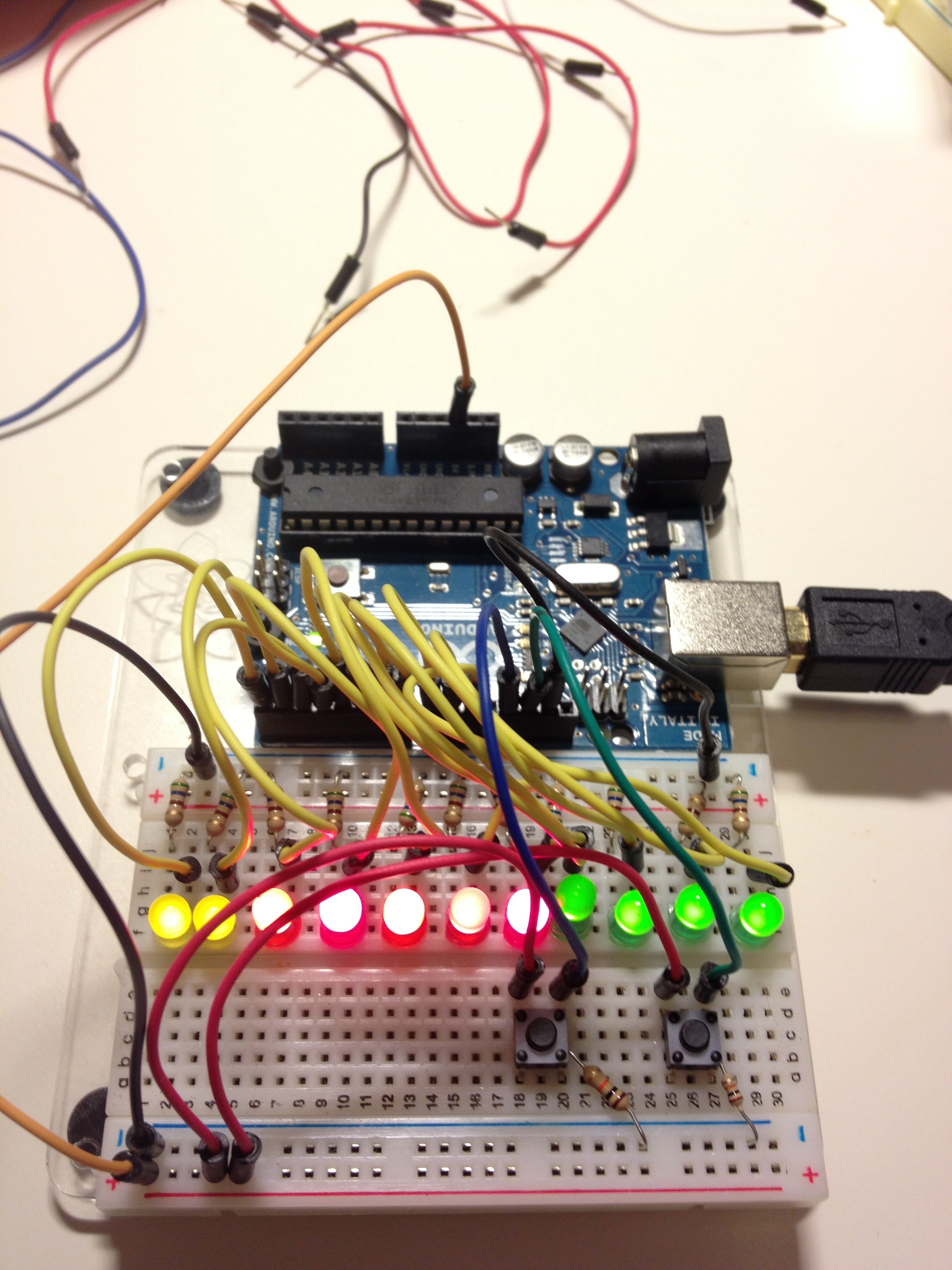
 Breadboard Prototype: The breadboard prototype came together quickly. To ensure that I everything was working, I created a quick test sketch for the Arduino. It basically turned all the LEDs on and tested that the buttons were working as expected. This was to save time later. I didn’t want to be troubleshooting what I thought was a software bug when it was really a hardware issue.
- Software: I used an iterative approach when coding the software. I got the basic functions working and tested it out a bit, then made some adjustments and tested more. For example, the first version was too blinky and distracting–not a good for a device that is supposed to help one be productive–so I implemented some fading for the countdown timer.
- Testing: At this point, I had a working prototype. Before spending any more time or money on this project, I wanted to make sure it was something useful for me. The best way to find out was to take it to work and see if I liked using it throughout the day. There was a problem though, the breadboard prototype was a little to fragile, and it sort of looked like an explosive device. Not wanting to get escorted out of my office by security, I decided to make a version with a less bomb-like appearance.
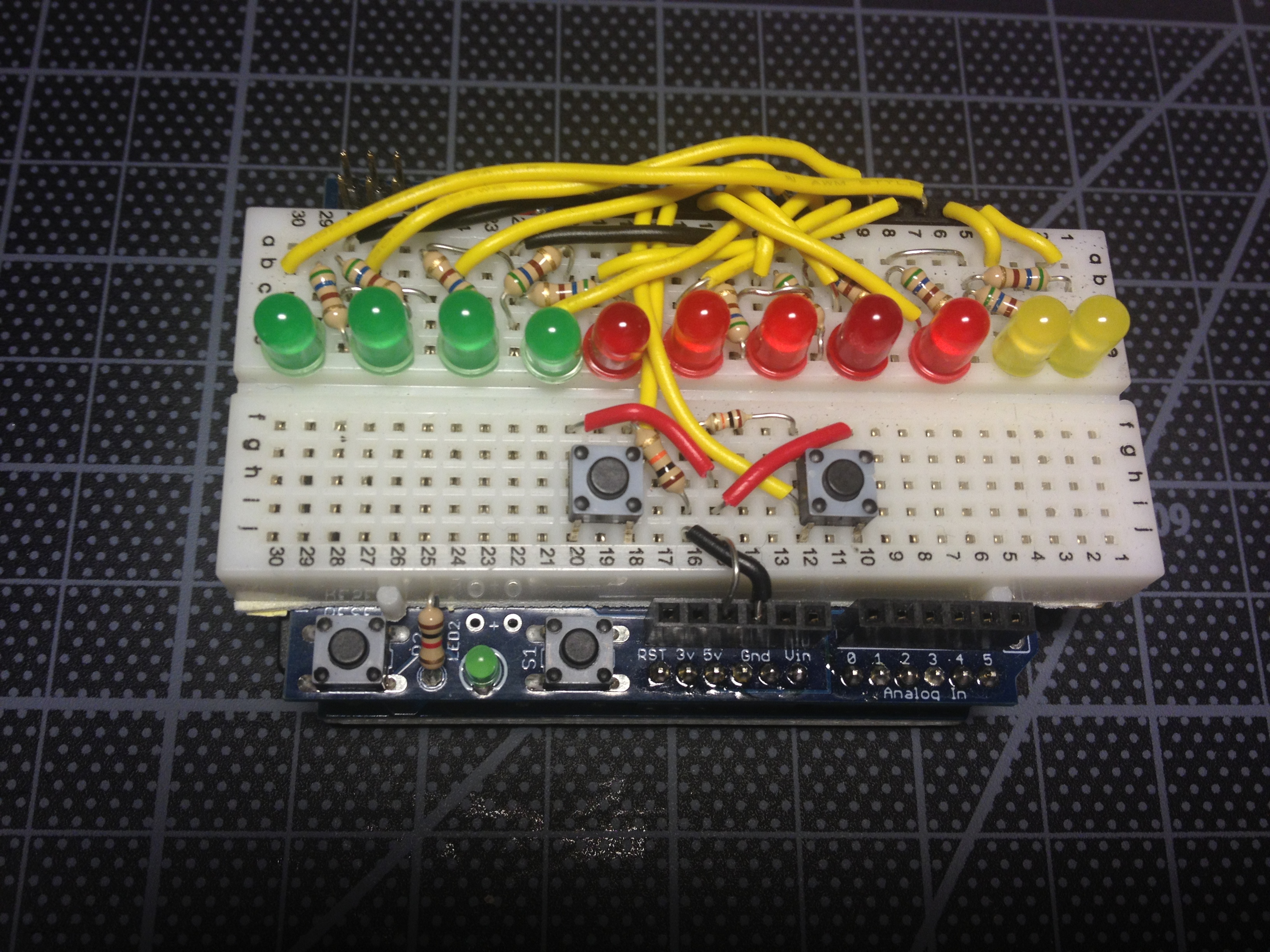
 I had an Adafruit proto shield to which I affixed a small breadboard. Instead of jumper wires, I used hookup wire. This made for a slightly cleaner appearance, and I didn’t worry about wires coming loose. It was a bit tight on the board though. In some cases, I used uninsulated wire because there wasn’t room for insulation. I could have made things a bit easier by rearranging my output pins in the software. This is something I ended up doing on the PCB, by the way. The end result, shown to the right, made for a good testing device.
 - Slight Change: After a few days of testing. I was happy with the way the timer was working. And, I also had some ideas about how to improve it. One of those ideas was a fairly drastic change to the design. So, I decided to move forward, but in a slightly different direction. Originally, I was going to build a little enclosure. Instead, I decided to make a shield for the Arduino. I did this both to get it done faster, and with the intention of building a different, fully enclosed, “version 2” in the future.
- Printed Circuit Board Layout: This was my first PCB. Eagle has a pretty steep learning curve, but there are many, many tutorials available. After finishing a tutorial or two, I started with the board layout from the Adafruit proto shield. This helped me get the measurements right. Even then, it took more time to lay the board out in Eagle than it took me to build and code the first prototype. The end result is worthwhile though, I learned a lot about Eagle and I’ll be faster the next time. As I mentioned earlier, I ended up changing some of the output pin assignments in the software to make the routing of the traces easier.
- Board Fabrication & Parts: The board diagrams were sent to OSH Park, which was a very simple process. I had some of the parts, but I wanted some nice new LEDs, which came from Adafruit. I like Adafruit for their well curated catalog and speedy delivery (especially here in New York City).
- Final Assembly:
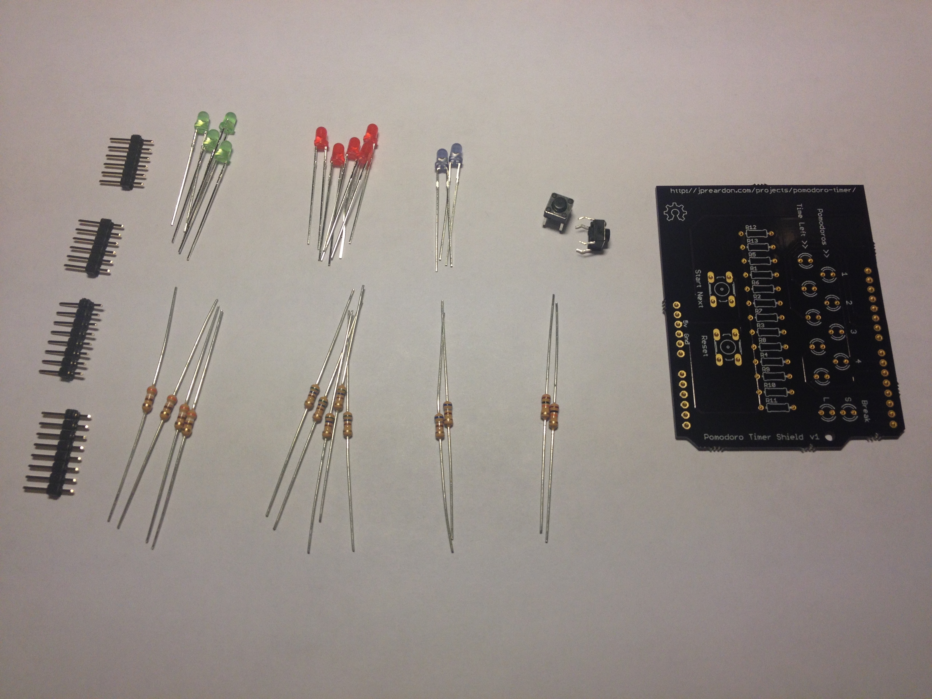
 It was really exciting to get the finished boards in the mail. They looked great! All that was left was the assembly. This was pretty straight forward as I had plenty of soldering practice on the Bose 901 EQ rebuild. The assorted parts are shown to the right, pre-assembly. I didn’t take any pictures while I was soldering, but I have two tips: 1) Start from the middle of the board, and work your way out. 2) A handy trick when soldering the headers on an Arduino shield is to use an Arduino to hold the headers in place.
 - Smoke Test: As I was soldering the last couple components on the board, I was getting a little nervous. I wasn’t sure if it would work at all. When I plugged the shield into the Arduino for the first time, nothing happened, not even a flicker, nothing… Crap. Basic troubleshooting revealed that the other end of the power supply wasn’t plugged in. Operator error. With actual power the timer worked (almost) exactly as designed. The only issue I had to fix was in the software–two of the output pins were mixed up.
Conclusion
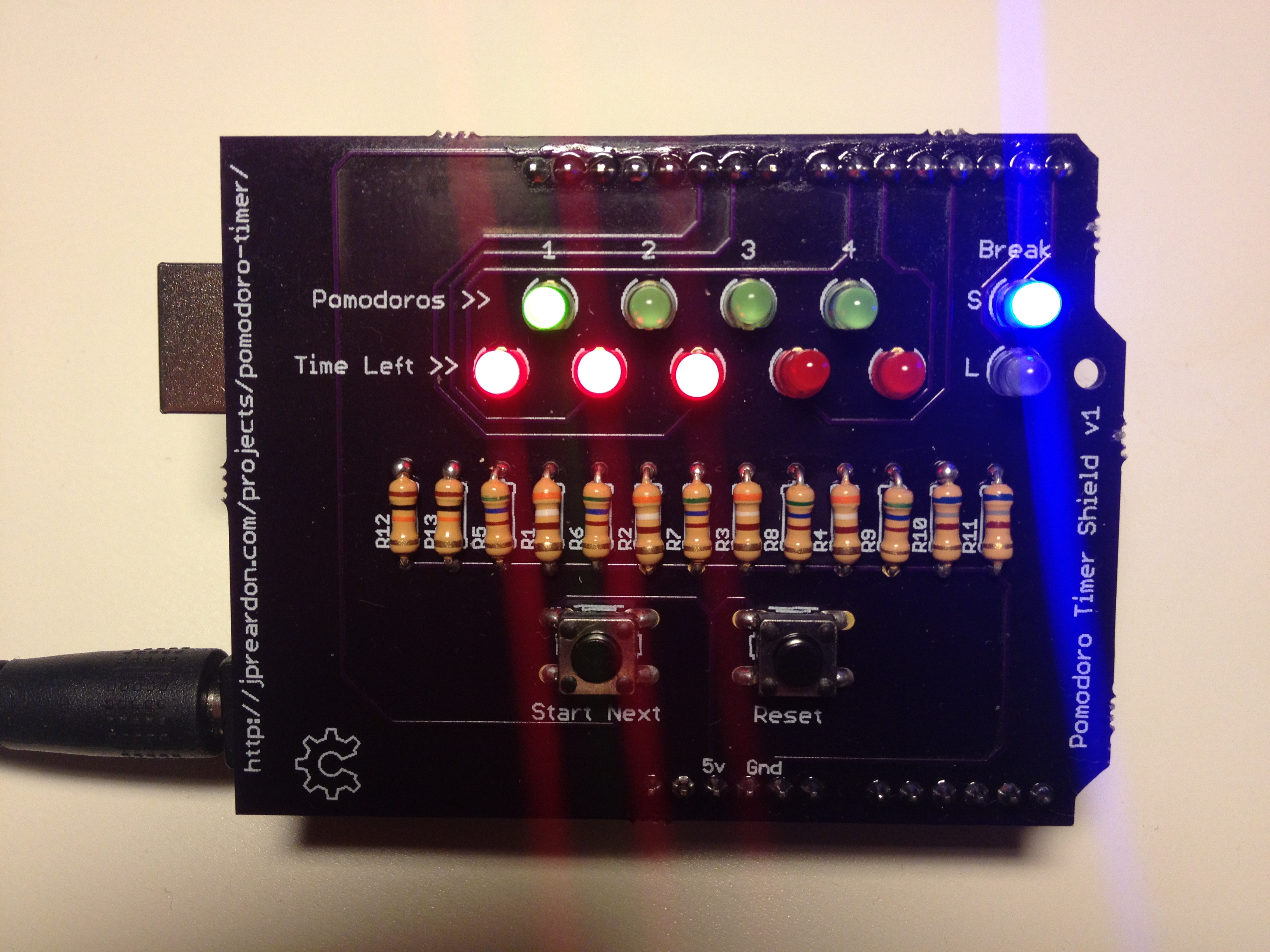
I use the timer daily at work, I used various bits of knowledge I’ve gained while experimenting with Arduino and electronics, and I learned some completely new things. So, I proclaim this project a success. The only thing I might do differently in the future would be to hold off on doing a schematic in Eagle until it was time to create the PCB. Of course, if the project called for a more complex circuit, a schematic early on would be a good idea.
While working on this, I had some ideas for how this project can be improved. For example, using a more “analog” type display for the countdown timer would be nice. Another idea was to incorporate some form of treat dispenser as it would be nice to get a piece of candy or a nut as positive reinforcement for keeping on task.
Speaking of treats, if you’ve read this far, you deserve one. If you have any questions or comments, please don’t hesitate to contact me.
Resources
You can find the Arduino sketch, schematics and board layout on Github.
This project uses an Arduino Uno. The PCB was designed using CadSoft Eagle and fabricated by OSH Park. All of the LEDs, switches and headers came from Adafruit while the resistors were from DigiKey.
If you’re new to Eagle, you will be well served by going through a tutorial before trying to create a board for your own project.
[…] Pomodoro Timer […]
[…] JP Reardon wrote in to share about his Pomodoro Timer project […]
[…] I’m not sure why a random post about a weather widget is so damn popular. It continues to be one of the most visited pages on this site. Although, in the last six months or so, it is has been been knocked out of the top spot by more informative posts such as Temperature Logging with Twine and ThingSpeak and Pomodoro Timer. […]